Overview of USB Wiring Diagram

Understanding USB Connectors and Cables
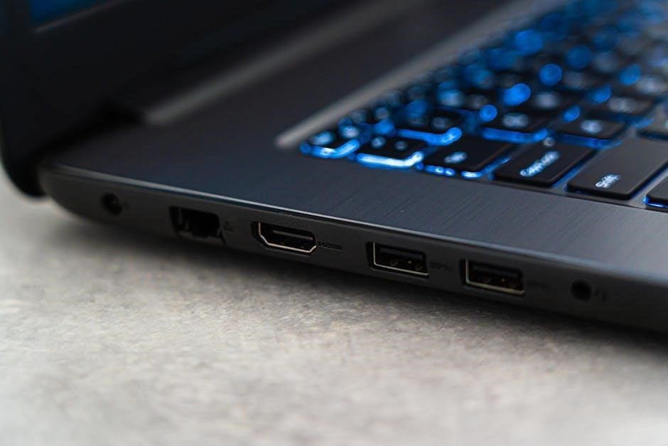
Types of USB Connectors and Their Pinouts
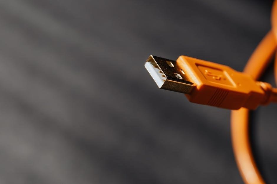
The USB-A connector has a specific pinout, with pins assigned for power, ground, and data transfer, while the USB-B connector has a different pinout, used for peripheral devices and other applications.
The USB-C connector, on the other hand, has a reversible design and a unique pinout, supporting faster data transfer rates and higher power delivery, making it a popular choice for newer devices and applications. This information is essential for understanding USB wiring diagrams and for working with USB connectors and devices, and is typically included in technical documentation and online resources, using HTML tags for clear and concise explanations.

Creating a USB Wiring Diagram
Steps to Draw a USB Wiring Diagram
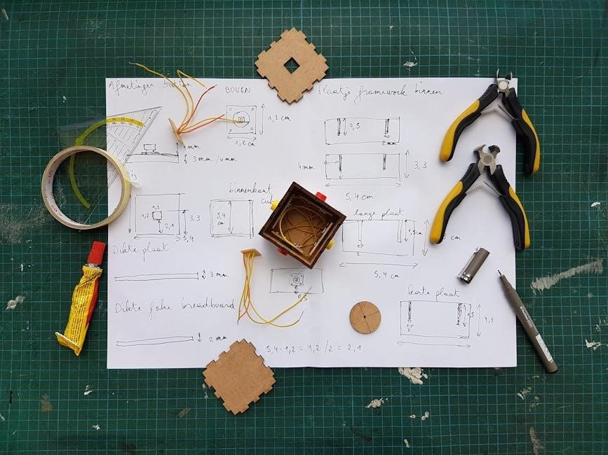
The steps involved include determining the type of USB connector, identifying the pinouts, and creating a detailed diagram with clear labels and symbols.
Using a diagramming tool or software, create a new document and add the necessary components, including the USB connector, cables, and any other relevant devices.
Follow standard conventions and guidelines for creating a wiring diagram, including using consistent symbols and notation.
Once the diagram is complete, review it for accuracy and make any necessary corrections.
Finally, save the diagram in a suitable format, such as a PDF, for easy sharing and reference.
By following these steps, you can create a clear and accurate USB wiring diagram that meets your needs and helps you to understand the complexities of USB connections.

Interpreting a USB Wiring Diagram PDF
Understanding the Symbols and Notations Used
Applications of USB Wiring Diagrams
Troubleshooting and Repairing USB Devices


